
Floppy Disk Drive
- Introduction
- A floppy disk is a secondary storage device.
- It is a means of storing data in a ring thin film of electromagnetic material housed inside a plastic cover.
- The data available in a floppy disk can be read by using a Floppy Disk Drive
Floppy Drive Components
- Motors
- Sensors
- Electronic circuit board
- Locking mechanism
- Read write head
- Power Connector
- Floppy Disk Controller
- Stepper Motor
- It is used to move the media and bring the read/write head to the desired track.
- Spindle Motor
- It rotates the floppy disk when it is placed inside the FDD.
Sensors
- It is used to identify if the floppy is write-protected, verifying if the read/write head is positioned at track0 etc.
- There are five sensors in a Floppy disk drive.
- Disk Change Sensor - It perform only at the time of disk changing.
- Track 0 Sensor - It sense the head has . arrived to track zero.
- Write Protect Sensor - It sense whether the disk has been write protected or not
- Index Hole Sensor - It sense the arrival of the first sector in each track
- Media Sensor - It Sense to find the disk type.
Electronic Circuit Board
- It Control The Read And Write Operation. It has Two types:
- 1. Read logic Circuit
- 2. Write logic circuit
- Locking mechanism
- It present only available in the 51\4 floppy drive.
- It sense whether disk has been inserted or not Read write head
- It perform for the read and write operation
Read / Write Head
- FDD has two read/write heads capable of reading from both the sides of the media.
- The read/write head is used to convert the digital data into magnetic pulses and vise versa.
- Two tunnel erase heads are used to delete the magnetic data that is written outside the defined track.

Power Connector
- The electronic components require +5V.
- The mechanical components need +12V.
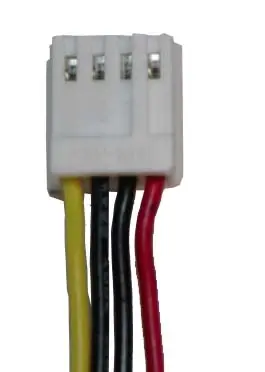
- FDD has four wires.
| Pin # | Description |
| 1 | +5 V Red Color Wire |
| 2 | Ground Black Color Wire |
| 3 | Ground Black Color Wire |
| 4 | +12 V Yellow Color Wire |
Floppy Disk Controller
- It is an interface between the processor and the floppy disk drive
- The multi function card contains the controllers for Floppy disk, hard disk, one parallel port, two serial ports and the joystick interface.

Interface Connector
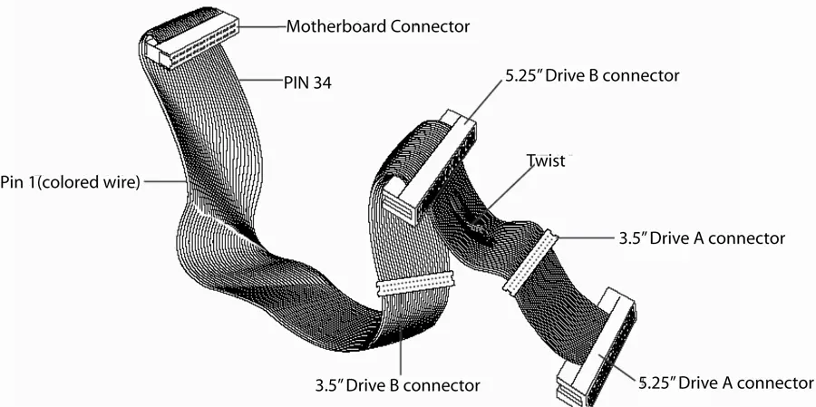
- The interface cable has 34 wires and it has five connectors.
- When a floppy disk drive is connected after twist then it is “Drive A” and if it is connected before the twist then the drive is “Dive B”.
Structure of Floppy Disk
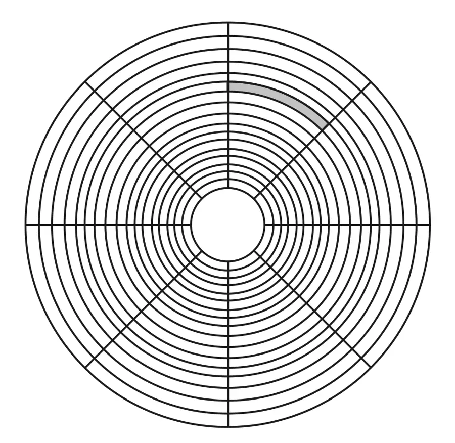
- It is a thin Mylar film with electromagnetic material impregnated in them.
- It can store data on either side.
- It is organized into tracks and sectors.

Write Protect Notch
- If Write Protect Notch is present in the disk, the other users can only read the data present in the disk.
- To write protect a 3 ½ floppy disk the notch on the bottom left corner should be opened.

Read/Write Head Slot
- The shutter opens automatically when the disk inserted inside.
- The read write head of the drive comes in contact with the magnetic film.
- Drive hub ring
- The hub is present in the center of the disk.
- It is used to hold the disk at center on the drive shaft.
Density Notch
- The density notch is present in the bottom opposite to the write protect notch.
- The density notch indicates if the floppy is a high density floppy one.

Classification of Floppy Disk
| Characteristics | 360 KB | 720 KB | 1.2 MB | 1.44 MB | 2.88 MB |
| Size | 5 ¼ inch | 3 ½ inch | 5 ¼ inch | 3 ½ inch | 3 ½ inch |
| No. of Sides | 2 | 2 | 2 | 2 | 2 |
| Spindle Motor Speed | 300 RPM | 300 RPM | 300 RPM | 300 RPM | 300 RPM |
| No. of Tracks | 40 | 80 | 80 | 80 | 80 |
| No. of bytes / Sector | 512 | 512 | 512 | 512 | 512 |
| No. of Sectors | 9 | 9 | 18 | 18 | 36 |
| Density | Double Density (DD) | Double Density (DD) | High Density (HD) | High Density (HD) | Extra High Density (EHD) |
The capacity of a floppy disk can be calculated as follows
- Capacity= No. of tracks * No. of sectors/ track * No. of sides * Bytes stored in one sector
- No. of sides = 2 and Bytes stored in one sector = 512
- Capacity = No. of tracks * No. of sectors / track * 2 * 512
- For example if we consider 3.5 inch high density floppy
- Capacity = 80 * 18 * 2 * 512 Bytes
- = 80 * 36 * 1/2 KB (since 512 bytes = ½ KB)=1.44 MB
Methods of Formatting:
- Low Level Formatting
- It is the process of creating structures like the tracks and the sectors to store data in them.
- High Level Formatting
- It is the process of creating file system, root directory and the File Allocation Table.
Floppy Disk Drive Troubleshooting
| Problem | Solution |
| The floppy disk drive LED always stays on | The interface cable or the power cable may be connected reverse |
| Unable to boot with a System Disk | Change the Boot Sequence in the BIOS feature setup option in the CMOS to access Floppy Disk Drive (eg, Boot Sequence A,C,SCSI) |
| Write Protect Error | Check for the Write protect notch in the floppy disk. If the notch is open then the disk is write protected. If the notch is closed then it is possible to write to the disk.\ Write Protect sensor may be bad |
| Sector not found error | Floppy Disk is bad or disk is dirty and needs to be cleaned. |