
System
- Familiarisation
System Familiarization
- Overview
- The components of computers are electronic and electro mechanical.
- Computer is used to perform arithmetic and logic operations.
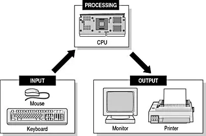
The block diagram of a Computer
- The input is given by the user using input devices.
- Input is stored in memory and then brought to the CPU for processing
- The result is brought back to the memory for storage and given to the output
Parts of a computer
- Input devices
- Output devices
- System unit
- Mass Storage Device
- The unit components
- Motherboard
- Microprocessor
- Coprocessor
- Memory
- Expansion Cards
- Power supply
Input Devices
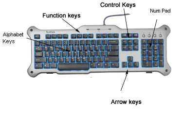
- Keyboard
- Keyboard is an input device used to input characters, numbers and special characters
- The keyboard connectors and the interface signals are given below:
- 5 Pin DIN Connector 6 Pin Mini DIN (PS/2)
Joystick
Joystick is an input device, which is used for playing games Mouse Mouse is an input peripheral device, used to open, close, copy, paste or do any formatting operations.

- Scanner
- Scanner is an input device, which scans text and graphics and sends to the processor for processing Light Pen
- Light pen is an input device. The light pen illuminated spot on the screen and an electrical energy is generated which is then sent as input to the system
Output Devices
- Monitor
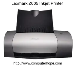
- The monitor is used to display the processed result Printer The output may be a soft copy or a hard copy.
- The printer provides the hard copy.
System Unit
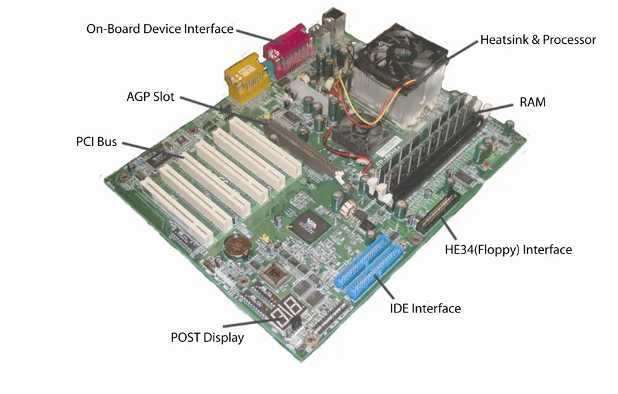
- Motherboard
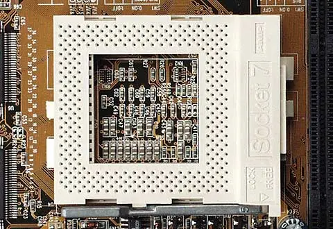
- It holds the CPU, and the other components in a computer.
Central Processing Unit
- (CPU)
- It is an electronic component with millions of transistors present in them.
- It reads the instructions from the memory and then decides on the operation that needs to be performed on the task.

Memory
Memory used in PC can be broadly classified into two types Primary Memory RAM – Random Access Memory ROM – Read Only Memory Secondary Memory Hard Disk Floppy Disk Magnetic Tapes CDs etc.
Primary Memory
- ROM (Read only Memory) is a Non volatile memory that stores the Basic Input Output System (BIOS) program and the hardware settings.
- RAM (Random Access Memory) is a volatile memory used for storing the user data temporarily when the CPU is processing information. RAM is of two types
- Static RAM (SRAM) used as Cache Memory
- Dynamic RAM (DRAM). DRAM used as main system memory
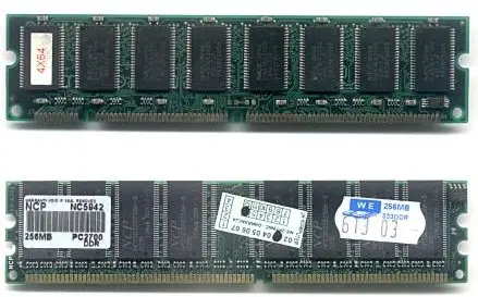
168 Pin Dimm SDRAM
- 184 pin dimm ddrdram

Memory Sockets
- The memory sockets can be either SIMM or DIMM.
- Simm slot
- Dimm slot


System Bus
- System bus refers to the bus which connects the CPU with the system memory Data Bus
- Data bus is bidirectional and the data is transferred to and from the CPU.
- The data bus is 64 bits which means that 8 bytes of data can be transferred at a time.
- 8 bits = 1 Byte
- 64 bits = 8 Bytes
- 1024 Bytes = 1 Kilo Byte (KB)
- 1024 KB = 1 Giga Byte (GB)
- 1024 GB = 1 Tera Byte (TB)
- 1024 TB = 1 Peta Byte (PB)
Address Bus
- The address bus is necessary to provide the address of the location where the data can be stored or retrieved Control bus
- The control bus is used to coordinate the data between the CPU and the peripherals devices or memory.
- Expansion Bus Slots
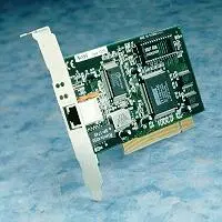
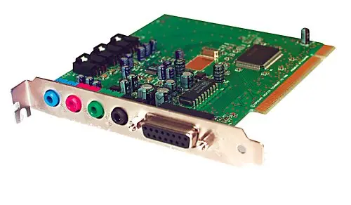
- The Expansion slots are used to hold add on cards or interface cards. It has Mainly Classified into three types.
- ISA – Industry standard Architecture
- EISA – Extended Industry Standard Architecture
- PCI – Peripheral Component Interface
Accelerated Graphics Port
- (AGP) slot
- It is employed for graphics card.
- Interface Cards
- It is used to grant access to various peripheral devices or the features.
Power Supply
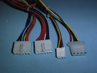
- The power supply unit in a PC is called as Switch Mode Power Supply (SMPS).
- SMPS is used to convert 110V /220V Alternating Current (AC) into 3.3V, 5V, 12V Direct Current (DC) supply.
- ATX Power Supply
- AT Power Supply

Storage Devices
- Floppy Disk
- The floppy disk is a removable disk that stores the data in a magnetic media.
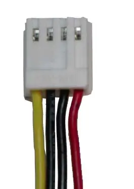
- A four pin Berg connector is used to provide power supply to the floppy disk drive.

Hard Disk
- It is a magnetic storage device.
- It is used store large amount of data in a PC.
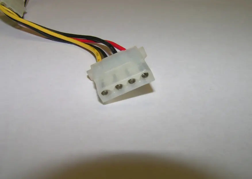
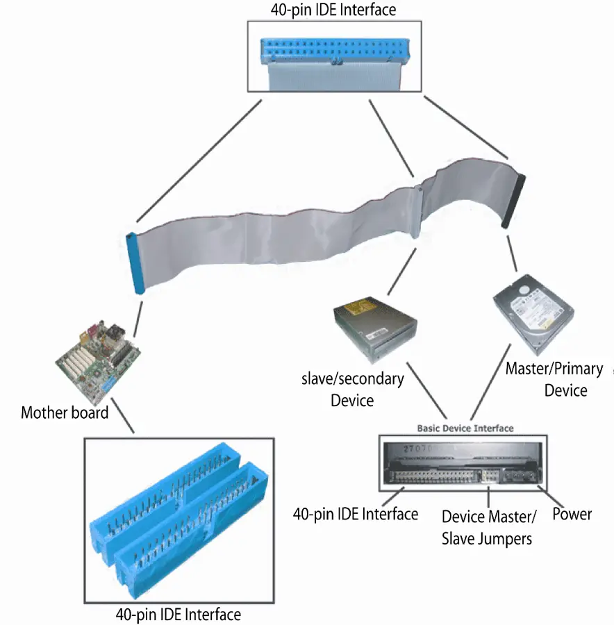
- The Power connector used for hard disk drive is a 4 pin called the molex connector.
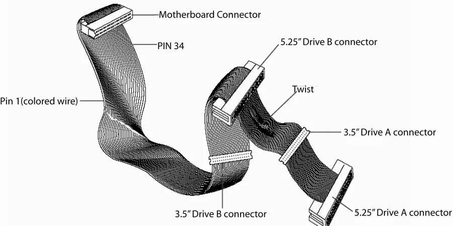
- The hard disk is connected to a 40 Pin Integrated Drive Electronics (IDE) Controller.

Compact Disk
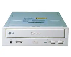
- It is an optical storage device, which uses LASER beam to read and write the data.
- The CD ROM drive can be connected to an EIDE controller on the motherboard.
- Zip Drive
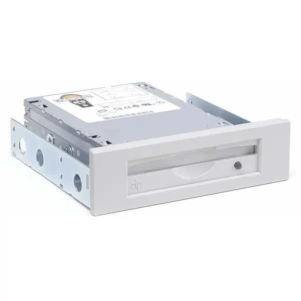
- Zip drive is a high density removable media which can store a maximum of 100 MB to 250 MB of data.
- Compact Disk
- CD Rom
- Zip drive

Tape Drive
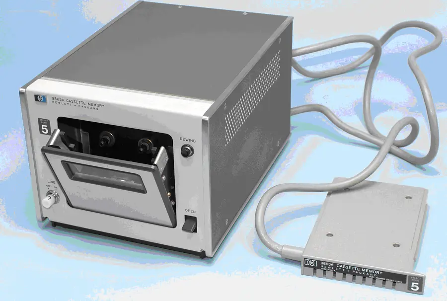
- It is used to read data and write data into a tape Pen Drive
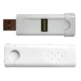
- A Pen drive is a flash memory data storage device integrated with a USB.
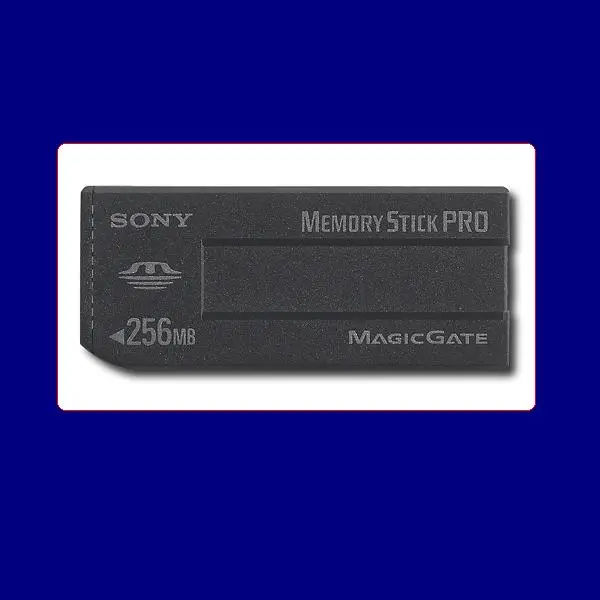
- Memory Stick
- It is a memory storage device in a laptop.
- Tape Drive
- Pen Drive
- Memory Stick
Peripheral Connectors
- 9 pin D type Serial port is uses for connecting any serial device
- 25 Pin D type female port is used for connecting Printers
- 15 Pin D type Female Connector is used for connecting devices like Joystick

Xt – Mother Board
Microprocessor
- Overview
- It is a single chip CPU.
- It is an electronic component integrated with thousands and millions of transistors for performing arithmetic and logic operations.
- The first processor under Advanced Technology is 80286. 80386, 80486 and the other Pentium processors.
- The CPU is made of two units namely the Arithmetic and Logic Unit and the Control Unit
- It performs functions like executing the instructions given by the user program, controlling the I/O operations and the functions of peripheral devices.
- The Arithmetic and Logic Unit (ALU) is used for performing Arithmetic and logic operations
- The Arithmetic operations are addition, subtraction, multiplication and division.
- The logic operations are taking decision based on same conditions.
- Block diagram of Microprocessor
- 1968 – intel formed
- 1969 – A Set of customizes chips
- 1971 – 1st Micro processor designed by TED HOFF 1972 – 4004 - 4 bit numeric 1972 – 8008 - 8 bit
- 1974 – 8080 - 8 bit numeric/alpha numeric 1976 – 8086 - 16 bit.
- 1978 – 8088 - 16/8 bit. The 1st PC introduces.
Features of 8086 Microprocessor
- 8086 is a 16 bit microprocessor
- The clock speed varies from 4 MHz to 10 MHz The data bus width is 16 bit
- The width of the address bus is 20 bits.
- Operates with +5V DC power supply
- It is a 40 pin DIPP Package
- It has a pipelined architecture
- Does not provide a coprocessor support
Features of 8088 Microprocessor
- The data bus is 8 bit.
- The clock speed supported is 4.77 MHz
- It supports the 8087 coprocessor
- Supports DMA data transfer
- Supports pipelined architecture.
- Supports nine flags
- Provides large number of I/O ports up to 64K
- The 8088 microprocessor operates in two different modes.
- Minimum Mode
- Maximum Mode
- The pin MN/MX decides the mode in which the processor can operate.
- Under Minimum Mode, there is no coprocessor support.

- Basic units of 8088 Microprocessor
- Bus Interface Unit (BIU)
- Execution Unit (EU).
- Functions performed by the BIU
- I/O read and write
- Memory read and write
- Address generation and storing pre-fetched instructions
- Functions performed by the EU
- Decoding the instructions fetched by the Bus Interface Unit
- Executing the instructions to generate the result

Co-Processor 8087
- Used for performing arithmetic, trigonometric, exponential and logarithmic instructions.
- So it is termed as Numerical Data Processor (NDP).
- Working of 8087 Co-Processor
- The results of floating point operations are desired to have 18 decimal digit accuracy.

Support Chips Used in 8088
- Different support chips present in the 8088 Motherboard.
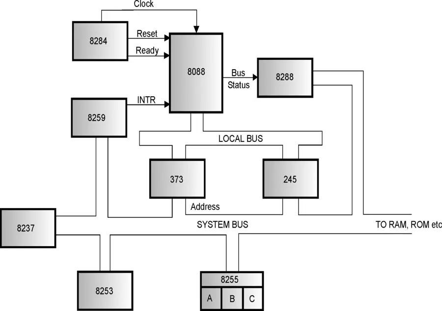
- Different support chips present in the 8088 motherboard.
- Classification of Support Chips
- Dumb Chip
- No intelligence and it is not programmable
- Does not have separate memory to store the commands and the controls
- Function of the dumb chip is fixed and is according to the input
- 2. Smart Chip
- It is programmable and has intelligence.
- Separate memory to store the commands and the controls
- Troubleshooting of a smart chip is complex
Supporting Chips
- Smart chip:
- 8255 (Programmable peripheral interphase (PPI)
- It Perform Keyboard interphase & Diagnostic code output for POST)
- 8253 (Programmable Interval Timer (PIT)
- It Generate speaker tones, Memory Refresh & Time
- 8259 (Programmable Interrupt Control (PIC)
- It Function a maskable interruption
- 8237 (Direct Memory Access Controller (DMAC)
- Main function is to transfer data from HDD or CDD DUMP CHIP:
- 8284 (CLOCK GENERATOR)- It perform in Clock, Reset and Ready Functions
- 8288 (BUS CONTROLLER) – It indicate the processor is ready to transfer the data to peripheral
Programmable Interrupt Controller (PIC) – 8259A
- It is used in the XT motherboard to generate an interrupt signal
- PCI is an interface between the CPU and the device.
- The XT motherboard supports one interrupt controller which can support eight devices

- The AT motherboard supports two interrupt controllers (8259) for supporting 15 interrupts.

- The snapshot shows the different IRQ channels associated with different devices.