WEEK 5
- Day 1 - serail and parallel ports
- (theory session)
- Day 2 - modem installation
- (demo session)
- Day 3 - input devices – (keyboard & mouse)
- (theory session)
- Day 4 - input devices – (keyboard & mouse)
- (demo session)
- Day 5 - printer
- (theory session)
Serial & Parallel Port
Overview
- I/O port is a channel that enables I/O devices to communicate with the system.
- A serial port is used to transfer a single bit of data at a time. Universal Serial Bus is connect different external devices
- CPU is uses the port to exchange data with other components.
Serial Port
- Introduction
- Serial ports can be used to connect any type of serial device like the mouse, modem, printer etc
- The different kinds of serial port are 9 pin D type Male connector and 25 pin D type Male connector from the system side.
- Difference between Serial communication and Parallel communication.
| Serial Communication | Parallel Communication |
| Serial communication is cheaper as it needs only one wire | Parallel communication is costly because it requires at least eight wires for transmission |
| Suitable for long distance communication | Not suitable for long distance communication |
Difference between Serial communication and Parallel communication
| Serial Communication | Parallel Communication |
| The length of the wire required for transmitting data is less | The length of the wire needed for transmission is more(8 wires) |
| Speed of transmission is less | Speed of transmission is high |
| Example Modem | Example Printers |
Parallel Data Transfer – Needs N separate Wires for sending N bits of data.
- Serial Data Transfer requires only one cable to transfer N bits of data
- Bit 0
- Sender
- Bit 7
- Bit 0
- Receiver
- Bit 7
- Media
- Sender
- Receiver
- Media
- Data
- Data
Serial Communication Modes
- Two communication modes for sending data Synchronous mode Asynchronous mode
| Asynchronous Communication | Synchronous Communication |
| Simple and Cheap method of communication | Communication between high speed buffered devices and hence costly |
| More overhead than synchronous communication since two or three bits per character are used for synchronization | The data is sent continuously and is faster. Provides better efficiency |
Types of Communication Modes
- Simplex Communication
- The communication channel can transfer data in only one direction.
- It is a permanent unidirectional communication.
- This mode does not allow acknowledgement to be sent back to the sender.
- Used for broadcasting.

- 2. Half Duplex Communication
- In this mode communication can send data in both directions but not simultaneously.
- The receiver detects the error in the data and asks the transmitter to send the corrupted data again.

- 3. Full Duplex Communication
- This mode permits data to be sent and received by the same communication channel simultaneously.
- Telephone is the best example for this mode.

RS 232C Standard Interface
- RS 232C is a standard interface designed by Electronics Industries Association (EIA)
- It follows negative logic.
- Modem uses the RS-232C interface standard.
- Modem is connected to the computers at both the ends
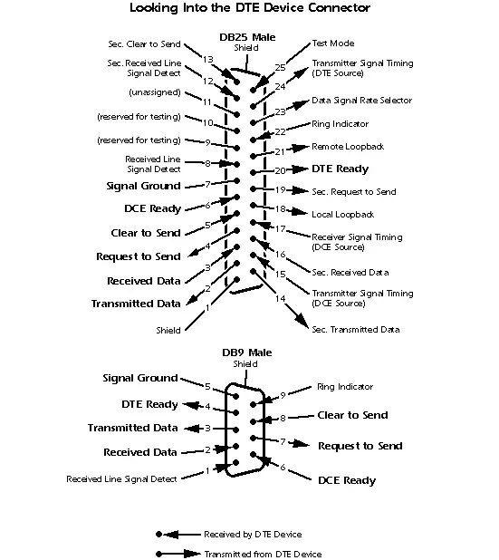
The DTE is provided with 25 pin D type male connector
- The modem (DCE) is provided with 25 D type female connector.
Null Modem
- If the distance between the two DTE equipments is less
- Then connect the two DTE directly without using modem
- The Request to Send (RTS) and the Clear To Send (CTS) signals should be short on both the transmitting end and the receiving end.

- The I/O address is a pathway for the processor to send data to the device or vice versa.
- IRQ is used to catch the attention of the processor.
- The BIOS configurations should be as shown in the figure

Connectors
- The 9 pin D type Serial connector
- The 25 pin D type serial connector
| Purpose of the Signal | Signal | PIN NO | DTE (PC) | DCE (Modem) |
| Data | TxD | 3 | Output | Input |
| RxD | 2 | Input | Output | |
| Handshake | RTS | 7 | Output | Input |
| CTS | 8 | Input | Output | |
| DSR | 6 | Input | Output | |
| DCD | 1 | Input | Output | |
| STR | 4 | Output | Input |
| Purpose of the Signal | Signal | PIN | DTE (PC) | DCE (Modem) |
| Data | TxD | 2 | Output | Input |
| RxD | 3 | Input | Output | |
| Handshake | RTS | 4 | Output | Input |
| CTS | 5 | Input | Output | |
| DSR | 6 | Input | Output | |
| DCD | 8 | Input | Output | |
| STR | 20 | Output | input |
Parallel Port
- Introduction
- A port is a set of signal lines.
- The parallel port was designed to communicate with the printer
- A parallel port female connector has 25 pins
Parallel Data Communication
- The PC permits point A to send data to point B
- Many interfaces have been designed to transmit different types of data accurately.
- By using an eight wire connector the parallel port greatly increases transfer speeds.

Devices Supported by Parallel Port
- The latest parallel port permits high-speed bidirectional communications
- Network adapter, high-capacity floppy disk drives, CD-ROM drives, backup units are attached to the parallel port
- Parallel ports are used to connect SCSI device to a PC.
- Connectors
- Parallel port is using a 36-pin connector on the printer side and a 25-pin D-sub connector on the PC side.

IEEE 1284-A has three types of connectors
- The type A connector is the parallel port connector
- The type B connector is called the Centronics connector
- MDR36, which is called type C
- Cables
- Any parallel device with an HPCN36 connector needs a 1284 cable. 0
Printer Controller
- The parallel port is actually called as printer controller
- It functions as a messenger between the CPU/BIOS and the printer
- Minimum 8 wires are required for parallel transfer of 8 bits.

- Centronics Interface - A computer and a printer get the handshake protocol between them by the Centronics Interface.
- It supports around 100kb/s data transfer speed.
- The interface of the PC side is a 25 pin D type connector

Signals from PC to Printer
- Twelve signals are there from the PC to printer.
- Among these 12 signals, eight signals are data bits and four signals are control signals.
- Control signals
- Strobe
- INIT
- Slct in
- Auto feed xt
Universal Serial Bus
- Introduction
- Universal Serial Bus is an I/O port is an external bus standard
- Used to connect different external devices like the external hard disk drives, printers, mice, scanners etc.
- The USB ports are generally present at the rear side of the PC along with the other I/O connectors
- USB ports can transfer data at 12 Megabits/second.
Features of USB Port
- USB standard supports many different types of devices
- A USB hub can be used to connect many devices by daisy chaining them.
- The USB cable has four wires. Two wires to carry power and ground and two wires to carry data.
- USB devices are hot swappable.


USB Connectors
- USB A connector
- It is used to connect devices where the cable is always attached.
- Hubs, mouse and keyboard are the examples USB B Connector
- It is used by devices which need detachable cables.
- Printers, scanners, modems, telephones and speakers are the examples
Working of USB
- The process of address assignment is called as enumeration. Three modes of data transfer in USB are Interrupt Mode – Transfers less amount of data at a time. Example: keyboard or mouse
- Bulk Mode - data is sent in large packets or blocks. Example: printer, scanner
- Isochronous - Data transfer is used by streaming devices like the speaker. Data is sent in streams between the device and the host
Devices supported by USB
- The devices supported by USB
- Printers
- Scanners
- Digital Camera
- Mouse
- Keyboard
- Speakers
- Modems
- Storage Devices like Zip drive
- Network Connections
- Joystick
- The different types of USB interface are USB 1.1 USB 2.0
FireWire IEEE 1394
- FireWire is a fast external bus standard.
- Two types of FireWire
- 1394a - data transfer is 400 Mbps
- 1394b - data transfer is 800 Mbps
- 1394 port can support a maximum of 63 devices
- Supports isochronous data and a high speed
- The maximum cable distance of an IEEE 1394 link is of 4.5 meters
Fire wire Connector
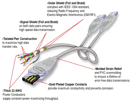
- The cable consists of six copper wires.
- Two wire carries power and four are grouped into two twisted pairs.
- The IEEE interface uses six conductors with two twisted pairs of wires used to carry data and one pair to supply power.
Devices supported by IEEE 1394
- Hard Disk Drive
- CD-ROM
- DVD
- CD-RW
- Tape Drive
- Digital Video Camera
- High Speed Printer and Scanner
- High speed mass storage
- Multimedia
- Comparison of some features of USB and Firewire.
- Ports and the device supported by them.
| Feature | Firewire | USB |
| Data transfer rate | 400 Mbps | 12 Mbps |
| Number of devices | 63 | 127 |
| Plug and Play | Yes | Yes |
| Feature | Firewire | USB |
| Data transfer rate | 400 Mbps | 12 Mbps |
| Number of devices | 63 | 127 |
| Plug and Play | Yes | Yes |
MODEM
Modems and Communication
- Introduction
- The most primary importance of the PC is communicating with other computers.
- You can access to the Internet at very high speeds by using various other alternatives to modem
Functions and Operation
- The data sent by the computer is in binary form.
- The data is modulated and is sent over telephone line.
- The data sent over telephone line is analog in nature.
- It is necessary to covert the digital data to analog form and to covert back to digital form.
- Components of Modem
- Modulator
- Demodulator
- Analog to Digital Converter
- Digital to Analog Converter
Asynchronous Serial Communication
- Asynchronous” means the modem that transfers data as needed
- It can transmit one byte of data at a time
- The actual data is surrounded by the start and stop bits
- Do not modify the settings of standard modem applications
Modem Types
- 1. Dial-up Modem
- It operates through a telephone line by running the telephone line to a modem in the personal computer
- Install dial-up modem in the computer
- The software in the computer controls the modem
- The modem calls the phone number and makes a connection
- Then the information is exchanged between the computer modem and the remote server
2. Internal Modems
- Expansion cards such as ISA, PCI or On-board are used
- While purchasing the modem, check for the compatibility
- Latest versions of Windows will detect the Win modem or Plug and Play modem

External Modems
- It is connected to the computer by a serial or alternate type cable
- A telephone line runs into the modem
- It is connected to the serial RS-232 or USB port and mostly has own power supply.

- 3. Integrated Services Digital Network (ISDN) Modem data transfer rates many times faster than standard PSTN connection.
- ISDN can use existing telephone cables.
- ISDN speed is consistent
- 4. ISDN Architecture
- Primary Rate Interface (PRI)
- Basic Rate Interface (BRI)
- 5. ISDN Hardware
- Supports phones, fax machines and computers.
6. Cable television (CATV) Network Modem
- It provides very fast Internet access and download speed can be 512 Kbps
- It uses copper-based coaxial cable
- The main trunks are fiber-optic; it is called a hybrid fiber/ coaxial (HFC) network.
- 7. Digital Subscriber Line (DSL) Modem
- It uses point-to-point solution
- It does not use a shared medium like a CATV network


Modem Standards
- The modem speed is calculated by BAUD rate in BPS (bits per second)
- Standard modem speeds are 300, 1200, 2400, 4800, 9600, 14,400, 28,800 bps
- The high speed modems’ speeds are 33,600 and 56,000